
Planning a Giant Fire Extinguisher Prop
Giant Fire Extinguisher Prop: one oversized static fire-extinguisher replica defined by a cylindrical tank, domed shoulder, valve and handle assembly, hose, nozzle, and supplied label field. Recognition depends on the tall cylinder, rounded shoulder, top valve, paired handle or lever, pressure-gauge cue, hose route, nozzle, base ring, and label placement. The central scale question is that the narrow top controls and hose must enlarge enough to read while the cylinder remains the dominant familiar safety-equipment silhouette. The images are fire extinguisher design concepts rather than photographs of completed WhiteClouds work.
Plan a Fire Extinguisher Display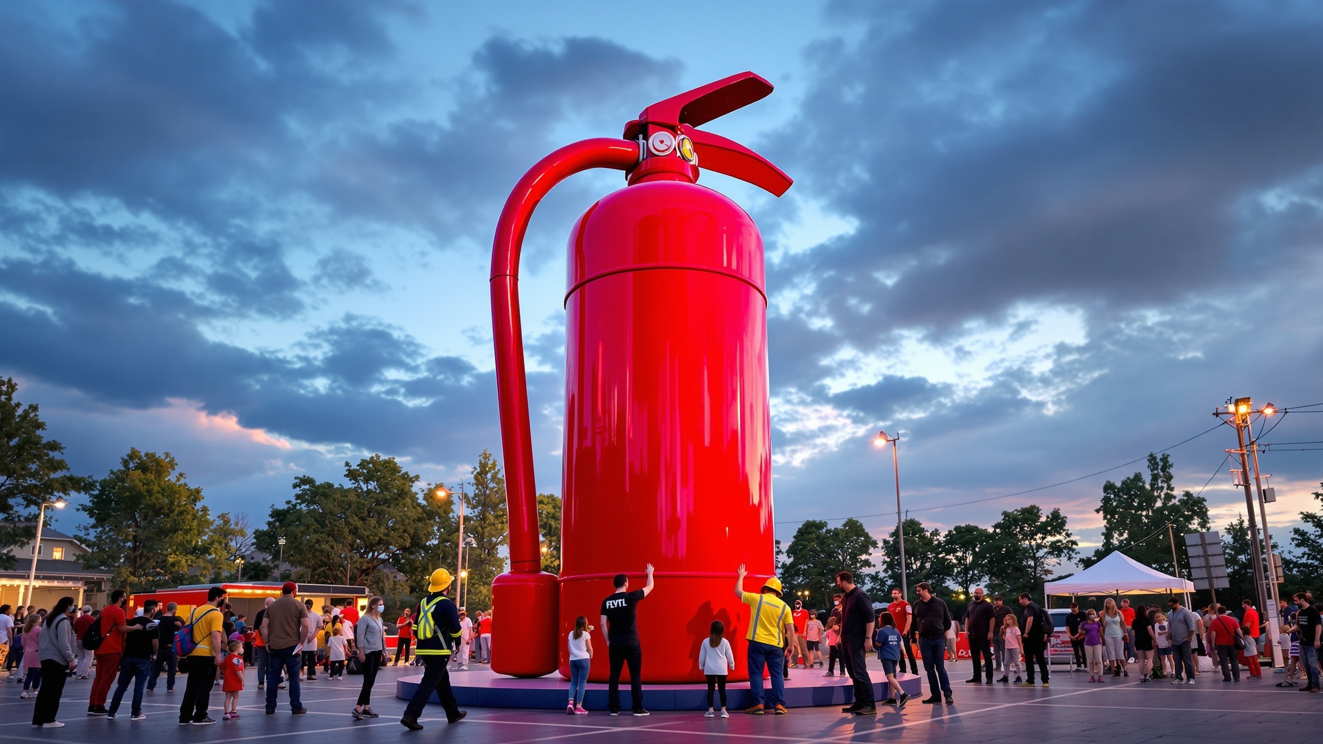
Define the Fire Extinguisher Form
Fire Extinguisher physical scope: one oversized static fire-extinguisher replica defined by a cylindrical tank, domed shoulder, valve and handle assembly, hose, nozzle, and supplied label field. Its geometry includes overall height and tank diameter, shoulder curve, valve height, handle span, hose length and path, nozzle size, base footprint, and display support. Its defining visual cues are the tall cylinder, rounded shoulder, top valve, paired handle or lever, pressure-gauge cue, hose route, nozzle, base ring, and label placement.
Fire Extinguisher presentation: a nonfunctional extinguisher-shaped display shown upright or at a defined angle with controls and hose visible but inaccessible for emergency use. The visual treatment can use approved extinguisher color, authorized label artwork, restrained metal-like control details, and hose-like visual treatment. Keep the fire extinguisher scope separate from fire suppression, pressurization, extinguishing agents, emergency placement, code compliance, certification, working valves or hoses, and invented safety claims.
The prop should be unmistakably scenic and never confused with emergency equipment. Start with tank profile, shoulder transition, neck, valve body, carrying handle, operating-lever silhouette, gauge location, hose attachment, nozzle rest, and base ring. A front elevation maps authorized label artwork; a side view controls hose path and handle projection. Define how the piece is identified as display-only and where it sits relative to real safety equipment. Familiar color and controls support recognition but do not establish pressure, contents, operation, or compliance.
A supplied label can carry much of the extinguisher identity, but the physical control cluster must still read from the chosen side. Map the valve neck, carrying handle, lever-shaped form, pin and seal-like cues, gauge position, hose connection, retaining clip, nozzle, and base ring without claiming that any part moves. The hose may hang against the cylinder, loop beside it, or follow a fixed scenic curve; each option changes the width and support area. The display should not imitate required emergency signage or occupy the role of actual safety equipment. Any nearby instructional content belongs to the exhibit plan rather than to the replica's operating capability.
Control the Details That Identify the Fire Extinguisher
Fire Extinguisher planning variables include overall height and tank diameter, shoulder curve, valve height, handle span, hose length and path, nozzle size, base footprint, and display support; the tall cylinder, rounded shoulder, top valve, paired handle or lever, pressure-gauge cue, hose route, nozzle, base ring, and label placement; approved extinguisher color, authorized label artwork, restrained metal-like control details, and hose-like visual treatment; and a nonfunctional extinguisher-shaped display shown upright or at a defined angle with controls and hose visible but inaccessible for emergency use.
Fire Extinguisher form
For the fire extinguisher, set overall height and tank diameter, shoulder curve, valve height, handle span, hose length and path, nozzle size, base footprint, and display support. Show one oversized static fire-extinguisher replica defined by a cylindrical tank, domed shoulder, valve and handle assembly, hose, nozzle, and supplied label field, and keep the complete outline readable from the primary approach.
Fire Extinguisher recognition
Preserve the tall cylinder, rounded shoulder, top valve, paired handle or lever, pressure-gauge cue, hose route, nozzle, base ring, and label placement. Rank the fire extinguisher cues for the expected viewing distance, and make every permitted simplification explicit.
Fire Extinguisher surface
Develop approved extinguisher color, authorized label artwork, restrained metal-like control details, and hose-like visual treatment. Place each requested fire extinguisher graphic on the reference views with usable artwork, orientation, and scale.
Fire Extinguisher setting
Plan a nonfunctional extinguisher-shaped display shown upright or at a defined angle with controls and hose visible but inaccessible for emergency use. Record the footprint and visible sides for the fire extinguisher, then add circulation around the fire extinguisher, access limits, support preference, and fixed site constraints.
Plan Scale, Viewing, and Placement
Fire Extinguisher scale issue: the narrow top controls and hose must enlarge enough to read while the cylinder remains the dominant familiar safety-equipment silhouette. Resolve that relationship through overall height and tank diameter, shoulder curve, valve height, handle span, hose length and path, nozzle size, base footprint, and display support, then test the fire extinguisher against its principal view and available floor or site area.
Fire Extinguisher settings may include safety or training exhibit; equipment or facilities campaign; trade-show, retail, stage, or photo setting. Useful buyer inputs include specific extinguisher reference; overall and tank dimensions; valve, handle, hose, and nozzle details; approved label artwork; display orientation; site and date. State any requested fire extinguisher contact, movement, lighting, or exterior exposure as a separate requirement.
Compare Fire Extinguisher Directions
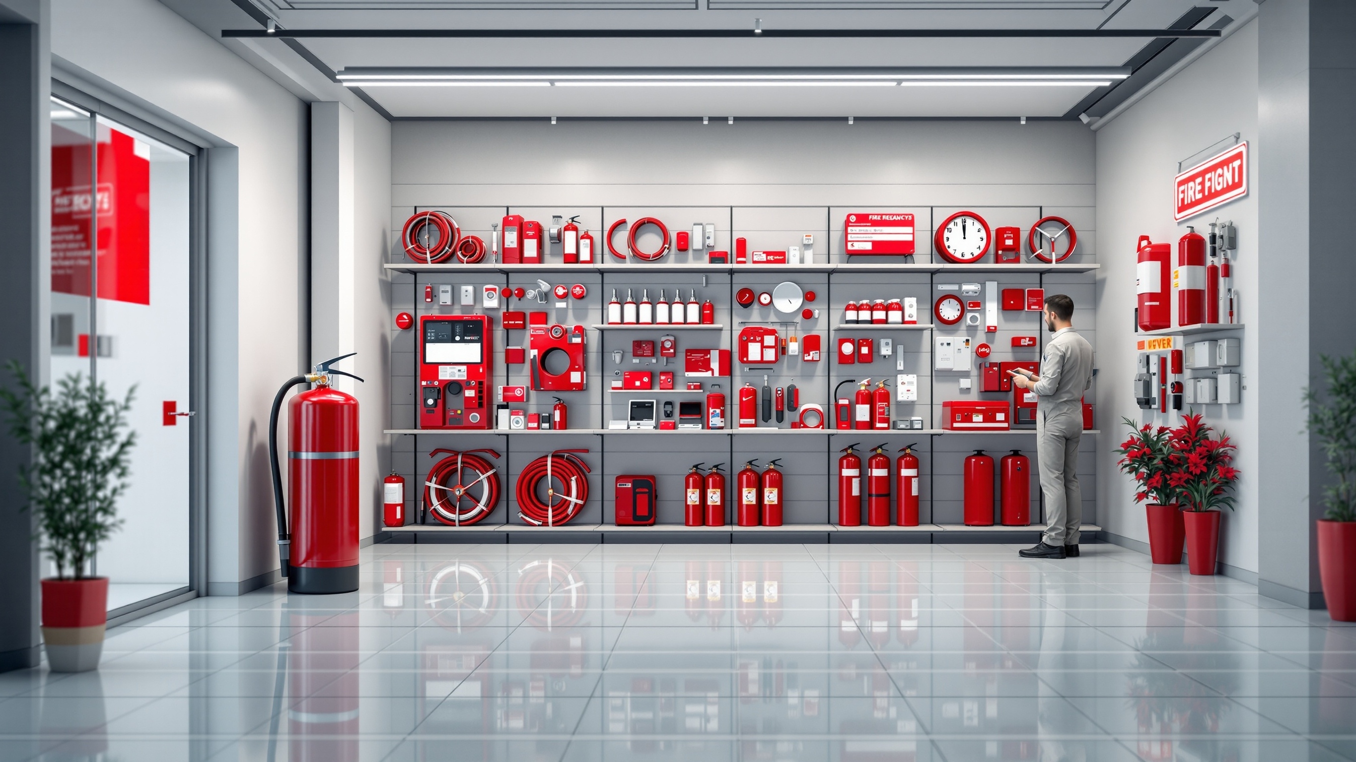
Fire Extinguisher reference 1: Shows the full equipment silhouette and human scale. Fire Extinguisher reference 2: Provides a cleaner reference for component placement and label area.
Compare the fire extinguisher concepts as visual directions. They do not identify a prior fire extinguisher customer or commission. Use the fire extinguisher views to compare overall height and tank diameter, shoulder curve, valve height, handle span, hose length and path, nozzle size, base footprint, and display support and approved extinguisher color, authorized label artwork, restrained metal-like control details, and hose-like visual treatment. The images do not establish final fire extinguisher dimensions, construction, performance, transport, installation, or outcome.
Prepare the Fire Extinguisher Project Brief
Fire Extinguisher quote inputs should connect the defining fire extinguisher cues with its intended dimensions and display setting. Include each applicable fire extinguisher item below.
- specific extinguisher reference
- overall and tank dimensions
- valve, handle, hose, and nozzle details
- approved label artwork
- display orientation
- site and date
- Physical subject: one oversized static fire-extinguisher replica defined by a cylindrical tank, domed shoulder, valve and handle assembly, hose, nozzle, and supplied label field
- Geometry: overall height and tank diameter, shoulder curve, valve height, handle span, hose length and path, nozzle size, base footprint, and display support
- Recognition cues: the tall cylinder, rounded shoulder, top valve, paired handle or lever, pressure-gauge cue, hose route, nozzle, base ring, and label placement
- Surface direction: approved extinguisher color, authorized label artwork, restrained metal-like control details, and hose-like visual treatment
- Display direction: a nonfunctional extinguisher-shaped display shown upright or at a defined angle with controls and hose visible but inaccessible for emergency use
- Scale issue: the narrow top controls and hose must enlarge enough to read while the cylinder remains the dominant familiar safety-equipment silhouette
- Fire Extinguisher setting: safety or training exhibit
- Fire Extinguisher setting: equipment or facilities campaign
- Fire Extinguisher setting: trade-show, retail, stage, or photo setting
- Excluded scope: fire suppression, pressurization, extinguishing agents, emergency placement, code compliance, certification, working valves or hoses, and invented safety claims
- Requested fire extinguisher contact, movement, lighting, or exterior exposure
Request a Custom Quote
Send the fire extinguisher reference, specific extinguisher reference, overall and tank dimensions, valve, handle, hose, and nozzle details, approved label artwork, display orientation, site and date, destination, and required date. Also describe a nonfunctional extinguisher-shaped display shown upright or at a defined angle with controls and hose visible but inaccessible for emergency use. WhiteClouds can review the defined scope and prepare a custom quote. The concept images support visual planning and do not depict a completed WhiteClouds project.