
3D Design for Custom Fabrication: From Idea to Usable Geometry
Turn references, drawings, and early concepts into a clearer digital model for fabrication planning.
A useful 3D design is more than a polished picture. It gives a fabrication team enough information to discuss shape, scale, detail, assembly, and the next practical step.
Technical Overview
What 3D design means in a fabrication project
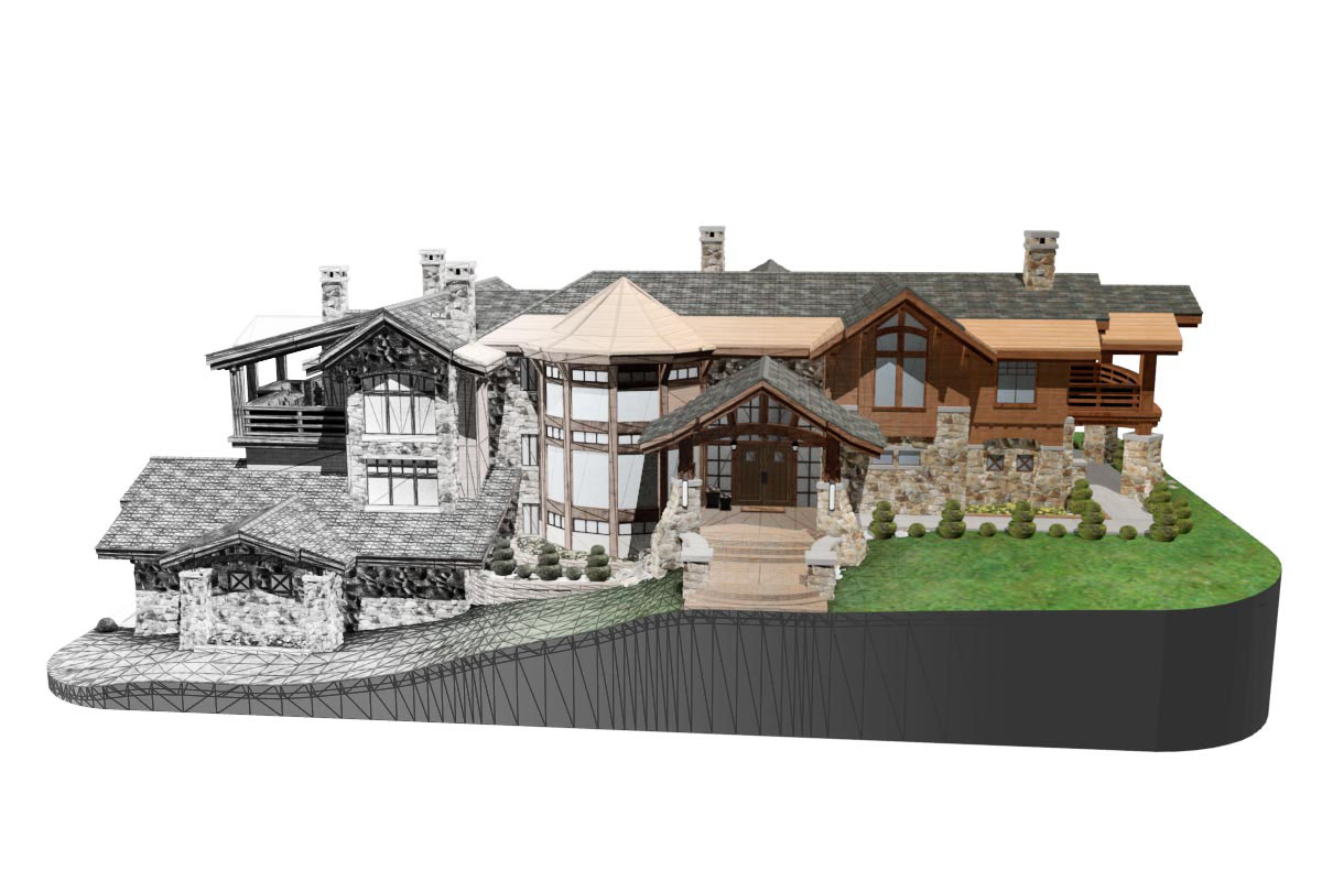
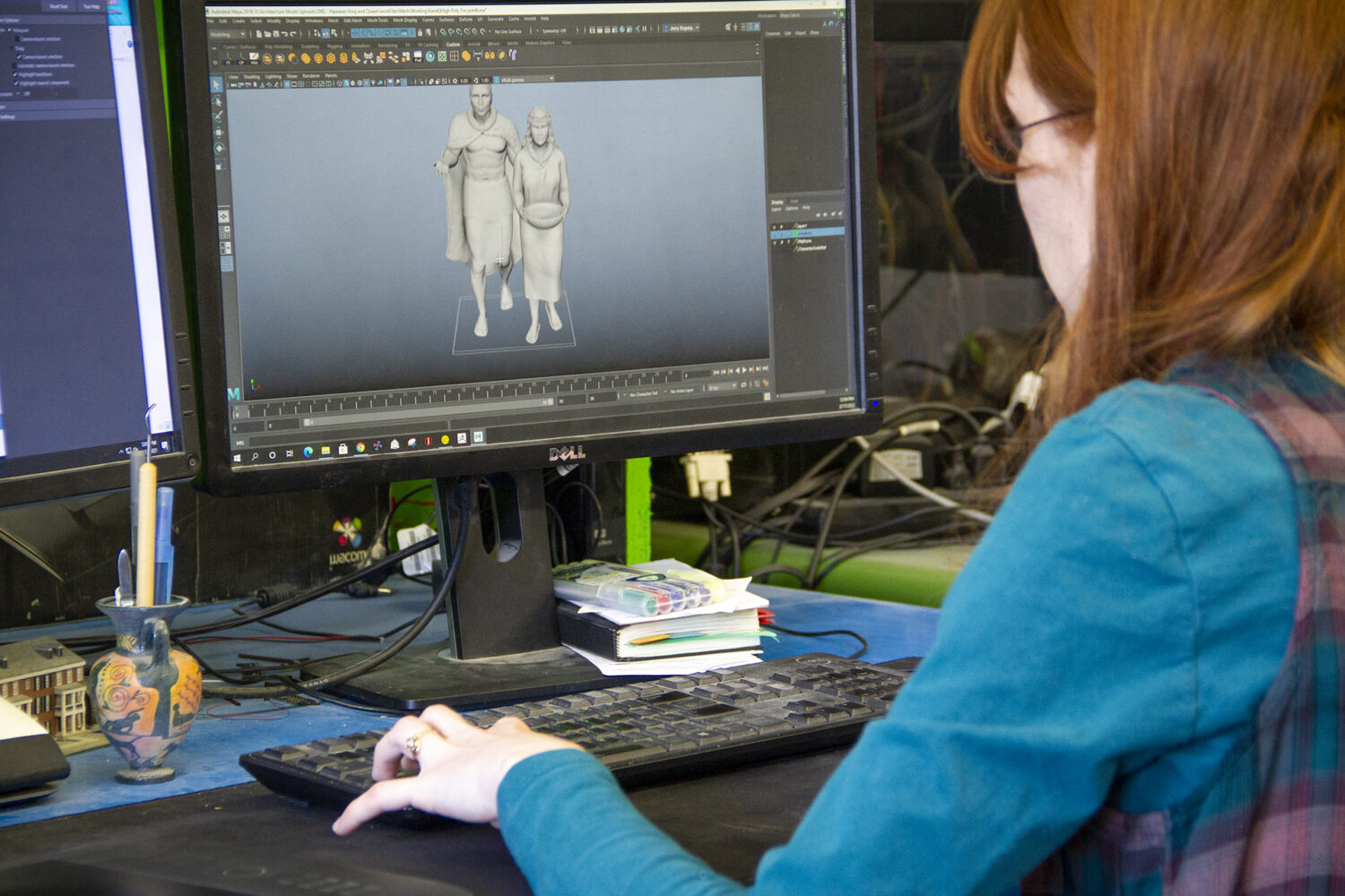
In a custom fabrication project, 3D design is the process of defining a physical form in digital space well enough to review and plan. The model may begin as a drawing, photograph, existing object, CAD file, or a rough concept. The work is to turn that starting point into a consistent shape with the proportions, openings, surfaces, and details the finished piece needs to communicate.
The right level of detail depends on the job. A large visual prop may need clear silhouettes and clean surfaces. A scale model may need more exact relationships between parts. A display with cutaways, removable sections, or a specific assembly sequence needs those decisions represented before fabrication begins.
Useful starting inputs
A complete CAD model is helpful, but it is not the only useful starting point. A design brief can include sketches, elevations, reference photographs, product dimensions, marked-up PDFs, logos, examples of the desired finish, and notes about the audience or viewing distance. A rough drawing is more useful when it includes at least one known dimension and identifies which parts matter most.
For an object with an irregular shape, several views can reduce guesswork: front, side, rear, top, and a perspective reference. If the model must match a real product or person, identify which features must remain recognizable and which can be simplified for the intended size and process.
Dimensions and scale are design inputs
Set the intended finished size early. A model that looks correct on screen may need different levels of detail when it becomes a large prop, a tabletop display, or a compact scale model. Note the overall height, width, depth, base or mounting area, access points, and any limits imposed by a doorway, vehicle, exhibit case, or installation site.
Viewing distance matters too. Details intended for close inspection may need different treatment from details that will be read across a room or photographed from a distance. A clear size target gives the design team a way to discuss which features deserve the most attention.

From visual concept to usable geometry
A rendered view communicates appearance, while the underlying geometry carries the shape decisions that fabrication depends on. Depending on the project, the review may address wall thickness, open or closed areas, joins between parts, hidden supports, orientation, and how the object will be divided or assembled. These are project-specific decisions rather than automatic properties of every digital model.
A design review is a good time to separate appearance questions from build questions. Confirm the silhouette, proportions, visible sides, surface detail, graphics, and finish direction first. Then identify the information still needed to plan fabrication, delivery, installation, or future revisions.
Review and approval checkpoints
A practical review sequence usually starts with overall shape and scale, then moves to detail, part breaks, surface treatment, and display requirements. Mark changes directly against a view or model version so the next revision has a clear target. If several people are involved, assign one person to consolidate comments before a revision is requested.
Before fabrication, confirm the version to use, the approved dimensions, the visible finish, the required accessories or base, and the delivery context. That short checklist can prevent a polished but outdated view from becoming the reference for the build.
Questions to include in a design brief
Describe what the piece is, where it will be seen, who will see it, and what must be recognizable. Add approximate dimensions, reference files, preferred materials or finish direction, interaction or lighting requirements when relevant, the installation setting, and the date the physical piece is needed. If the source is incomplete, say which decisions are still open.
That information gives a fabrication conversation a useful starting point. WhiteClouds can review the available references and discuss how the digital model should support the physical project.
Related 3D fabrication resources
Explore WhiteClouds custom fabrication services and examples of physical 3D props and models.
Tell us what your model needs to communicate
Share the intended audience, approximate size, level of detail, available source files, and project timeline.