
Transmission Scale Models
Custom physical models for explaining transmission and drivetrain assemblies
A transmission scale model can expose the relationship among gears, shafts, bearings, clutches, and housings. Its scale and level of detail should follow the mechanical path the audience needs to understand.

Technical Overview
What a Transmission Model Shows
A transmission carries power from an engine or motor to the driven components. By changing gear ratios, it changes the relationship among input speed, output speed, and torque. A physical scale model can make that arrangement easier to inspect by showing the housing and the positions of major internal parts.
The display does not need to reproduce every production component. It needs to show the parts and mechanical relationships that matter to the intended explanation, whether that means the overall assembly, a selected gear path, or a cutaway view of the interior.
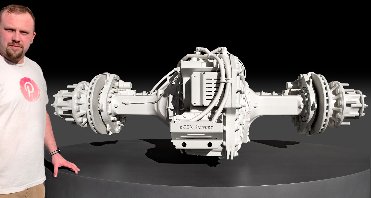
Transmission Types
Manual Transmissions
A manual transmission uses a clutch and driver-selected gear ratios. A model may need to show how the clutch, shafts, gears, and selector relate, or it may focus on the power path through one selected ratio.
Automatic Transmissions
An automatic transmission changes gears through hydraulic and electronic controls rather than direct manual selection. The project scope should identify whether the housing, gear train, control components, or their relationship is the main subject of the display.
Continuously Variable Transmissions
A continuously variable transmission changes ratio without a fixed sequence of conventional gear steps. A useful display needs to make the ratio-changing arrangement legible instead of relying on an exterior housing alone.
Dual-Clutch Transmissions
A dual-clutch transmission uses separate clutches for odd- and even-numbered gears. A physical model can be organized to distinguish the two gear paths and show how both sets fit within the assembly.
Define What the Model Must Explain
Before fabrication, identify which gears, shafts, bearings, clutches, controls, and housing sections must remain visible. Also decide whether the audience needs an exterior overview, a cutaway, or a closer view of one mechanism. Those choices determine the useful scale and level of detail.
Any requirement for movement, disassembly, or operating behavior must be stated in the project scope. A static display model should not be assumed to function like the production transmission it represents.
Scale and Source Information
CAD geometry, drawings, blueprints, and schematics can establish component shape and placement. The source files may need to be simplified so the selected parts remain readable at model scale and details that do not support the explanation are left out.
Scale should be chosen after the viewing distance and key components are known. A compact tabletop model and a larger presentation model may use the same source assembly but require different decisions about visible detail.
Fabricating the Display
Transmission models may combine digitally prepared geometry with machining, 3D printing, assembly, and finishing. The appropriate process depends on the component geometry, finished size, surface treatment, and whether parts need to remain exposed or separate.
The model should maintain clear alignment among the major components so the assembly reads correctly. Material and finish decisions follow the display requirements rather than the operating specifications of the full-size transmission.
Planning a Transmission Model
A useful project brief identifies the intended audience, the mechanism to be explained, the components that must be visible, the desired model dimensions or scale, available technical files, any movement or removable-part requirement, and the project timeline.
Explore industrial model resources
Review WhiteClouds industrial model capabilities and browse completed model examples.
Tell us what your model needs to communicate
Share the intended audience, approximate size, level of detail, available source files, and project timeline.