
Gearbox Models
Custom physical models for explaining industrial assemblies
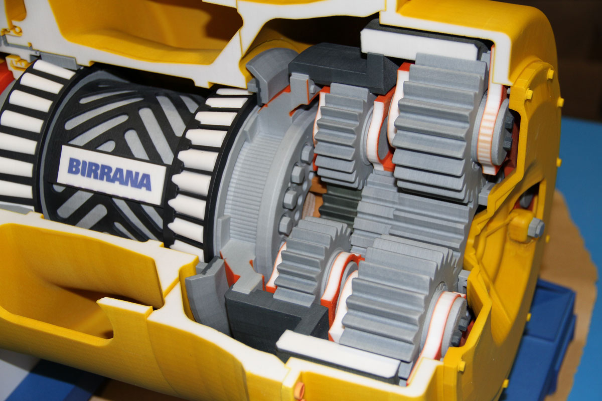
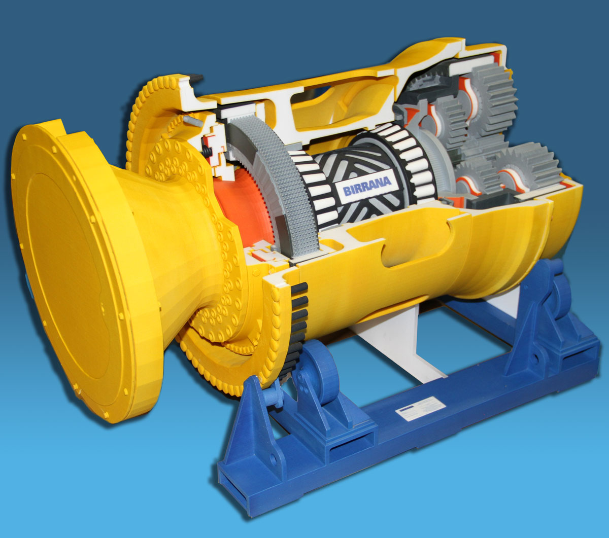
A gearbox scale model can show how gears, shafts, bearings, and housings relate inside a compact assembly. Its scale and level of detail should be chosen around the components and mechanical relationships the audience needs to understand.
Technical Overview
What a Gearbox Model Shows
A gearbox transfers power through an arrangement of gears, shafts, and bearings. Different gear ratios change the relationship between input speed, output speed, and torque. A physical scale model can make that arrangement easier to inspect by showing the housing and the position of the major internal components.
The word model can refer to the gearbox design itself or to a physical representation of that design. This guide focuses on the physical display model: what it may need to show, how gearbox types differ, and which inputs should be settled before fabrication.
Gearbox and Transmission Types
Manual Transmissions
A manual transmission allows the driver to select gear ratios through a gear lever and clutch. A model of this system may need to make the selected gear path and the relationship among the lever, shafts, gears, and clutch easy to follow.
Automatic Transmissions
An automatic transmission changes gears through hydraulic and electronic control systems rather than direct manual selection. For a display model, the brief should identify whether the housing, gear train, control components, or their relationship is the main subject.
Continuously Variable Transmissions
A continuously variable transmission changes the ratio without a fixed sequence of conventional gears. The source article describes pulley-and-belt and chain-drive arrangements. A useful model must make that changing relationship visually clear rather than relying on an exterior housing alone.
Dual-Clutch Transmissions
A dual-clutch transmission uses separate clutches for odd- and even-numbered gears. A physical model can be organized to show the two gear paths and how both sets fit within the assembly.
Define What the Model Must Explain
The model brief should identify which gears, shafts, bearings, seals, and housings must remain visible. It should also state whether the priority is the exterior form, the internal layout, or the relationship between specific components. Those choices determine the model's scale and the amount of detail required.
Any requirement for movement, disassembly, or operating behavior must be defined as part of the project scope. A visual display model should not be assumed to function like the production gearbox it represents.
Source Geometry and Model Scale
Fabrication begins with the available technical information. CAD geometry, drawings, blueprints, and schematics can establish component shape and placement. The files may need to be simplified so the finished model shows the intended relationships without carrying detail that will not be visible at the selected scale.
Scale should be chosen after the viewing conditions and key components are known. A compact tabletop model and a larger presentation model solve different communication problems, even when both are based on the same assembly.
Fabricating a Display Model
Gearbox scale models can be developed through CAD, machining, 3D printing, assembly, and finishing. The appropriate combination depends on the geometry, model size, required surface treatment, and whether parts must remain visible or separate.
Fit, alignment, and a clear visual hierarchy matter because the model has to explain a dense mechanical assembly. Materials, tolerances, and functional requirements should be set for the individual project based on what the model must show and whether any components must move or separate.
Explore industrial model resources
Review WhiteClouds industrial model capabilities and browse completed model examples.
Tell us what your model needs to communicate
Share the intended audience, approximate size, level of detail, available source files, and project timeline.